

See those three little black boxes? They are on-board relays. This is what i really like about MiniMS, it allows for a really neat wiring as there will be no relays to wire externally. It even has the fuses inside also.
Since it's based on Ver 2.2 schematic, it inherits some the specs which require me to make some minor changes as they're useless for my particular application on single cylinder motorcycle.

First of all, it uses an on-board MAP sensor MPX4250. This means there should be an access hole for a vacuum line to plug to the sensor. Not really a pretty sight. The Vixion throttle body assy i'm using already has its own MAP sensor that i'm planning to use. Herein lies a problem: the so-called automotive connector is a weatherproof 23 pin AMPseal connector and there are no readily spare pins that i can use to wire a MAP sensor signal line on it. Luckily, there is a solution. On the original design, pin 18 is actually for an "isolated ground from coil". This is meant for the screen wire from ignition coil to minimize interference. Since i'll be using an LM1815 VR conditioner externally, this pin is not necessary. I traced this pin to the PCB and it's not connected to anywhere so it's safe for me to remove the on-board MAP sensor and put a jumper wire from R2 (refer to MS v2.2 schematics) to pin 18 and that's exactly what i did. Keep in mind that for the sensor's +5V reference voltage, you can use the same pin for the TPS (pin 5).
MS v2.2 is not meant to control ignition without some mods. As such, i had to find another pin i can use for the ignition output as i want to avoid having a wire coming out of nowhere from the case. I chose to use the 2nd Injector Bank input on pin 23. I'll only be using one injector on this conversion so a 2nd Injector Bank is not necessary. To achieve this, i had to remove Q7 (IRFZ34 driver) and put a jumper wire from LED D17's cathode to pin 23. Since i'm planning to use my 4A-GE igniter module, i had to come up with a 5V pullup using 1K resistor. The 5V source i'm using is from C3 which is supplied to pin3 of the on-board MAP sensor. Then i wire R17 directly to ground to avoid floating the MC34151's pin 5 output. I might also be able to use the stock AC CDI module this way by wiring this ignition output to the pickup coil's input pin, triggering the internal SCR with a 5V pulse but i need to remove the timing capacitor first. I don't know if this is possible yet, so i'll update you on this later. Also, since pin 9 will no longer be used to supply 12v to the injector, i can use this for the O2 sensor's heater and LM1815 VR conditioner power supply.
Last thing i did is to put an SPST momentary switch for the bootloader jumper pins and mount the switch to the case. This is not really necessary especially if you're not flashing the CPU many times but knowing this project is still experimental, i figured it will be useful.
Below you can see the jumpers and the switch mounted to the case. Note that Q7 is still there and the ignition output wire is not yet wired to the AMPseal connector. You can also see the the 1K pullup resistor and the jumper for MAP sensor signal from pin 18.
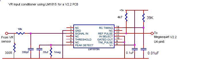
One note about using the LM1815 VR conditioner externally to the MiniMS. Unlike the suggested method of wiring the conditioner's output to pin 6 of the 4N25 optoisolator (base of the internal NPN transistor), i'll be wiring the output to MiniMS's pin 4, the coil (-) input of the AMPseal connector where eventually this will go to pin 1 of the 4N25 (anode of the internal LED) via R10 (390 ohms) while the Wing (D5) and John (D8) diodes are jumpered. This has been done on my 4A-GE before i switched to EDIS so it should work. Best of all, this method retains the opto-isolation as i'm not wiring the input directly to the CPU so it's safer.
To summarize the changes, i made this diagram below.

With all the changes done, here is the final pinouts of the AMPseal.
1. Injector 1 +12v
2. Fuel pump output +12v
3. DB9 pin 2 RS-232 data T1 out
4. Coil – terminal ---> INPUT from LM1815N
5. TPS +5v ---> Shared with MAP Sensos
6. Idle output +12v
7. TPS signal
8. Coolant temp sensor
9. Injector 2 +12v ---> Power supply to LM1815N and Oxygen Sensor Heater
10. DB9 pin 3 RS-232 data R1 in
11. DB9 pin 1 +5v
12. Ground
13. Ground
14. Oxygen sensor
15. Manifold temp sensor
16. +12v in battery
17. Ignition switch +12v
18. Isolated ground from coil ---> MAP Sensor Signal Input
19. Ground
20. Ground
21. Ground
22. Injector 1 -
23. Injector 2 - ---> Ignition Output to Igniter or CDI
http://megachorro.blogspot.com/
ReplyDelete