Click on each pic to for better view.
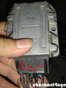
IGNITER

THROTTLE POSITION SENSOR (Connector View)

IGNITION COIL (Connector View)

MAP SENSOR

OXYGEN SENSOR
I am not using OEM Oxygen sensor which i believe is a two-wire type (confirm this please?). I am using a four wire O2 sensor taken from Kia Carnival and here's the pinout based on wire color on the sensor.

I won't be using the heater so i'll just use the two remaining: signal and earth.
DISTRIBUTOR

Above you can see the mess i am facing on doing the EFI wiring. That's how the wiring done when i got the engine. Let me describe a bit what i found inside the distributor. There should be 4 cables coming out from it: G1, G2, NE and G-. Once you open the distributor cap, you should see two pickup coils immediately, placed 180 degrees opposite each other and each has two cables coming out of it. Those are are the G1 and G2 pickup coils and you need to combine one cable from each pickup coil to form the G-. The remaining cables from each pickup will be the G1 and G2. I don't know which is G1 and G2 and also don't know if they're interchangeable. That's why i label them Gx and Gy on the diagram above. I am inclined to think that G1 and G2 are not interchangeable. G1 should be the pickup that lines up with the 1 tooth sync wheel at cyl 1 TDC compression. G2 should be the pickup that lines up with cyl #4 (360° crank from G1) TDC compression. Using that info, then Gx should be G1 and Gy should be G2 but don't quote me on this.
Now that we've got G1 and G2, NE would be the two cables coming out from the behind the rotor plate, you won't be able to see the NE pickup coil if you just open the distributor cap. The cables should be yellow and white. Yellow would be NE and white would be G- which should be combined also with the G- from G1 and G2.
So basically, there should be six cables and three will be combined to form G-. The other three will be G1, G2 and NE!
I think that's all the stuff that you need to be careful when wiring them in.
These following parts are non-polar, meaning you can wire them anyway you like it.
- Water and Intake Air Temperature Sensor
- Knock Sensor (only 1 wire so you can't be wrong)
- Fuel and Cold Start Injectors
- Start Injector Timing Switch
- Idle Up VSV

Dude :), the pictures... u started putting charmant4age on em :D lol, i will do mine respectively, my project will start rolling again as of this weekend coming, i have decided to do the cut method, its freaking cheap and takes maybe an hour or so... if it gets fudged up then i have no choice but to buy that plate, i found a really great video that i will share with you guys, hoping to steal a camera and go take some photos of what was done to swap the ends from start to finish, the guy that i contacted also has a charmant so i am very interested in doing this now, so with that i can start moving again with "Project D" lol, we have a bit to catch up on man, g-chat soon :P
ReplyDeleteLooking good there Edgar, looking forward for the next part!
ReplyDeleteI just wire my Distributor like the way you presented here and it worked, I've been struggling with this wiring for days now. This was very helpful thank you!
ReplyDeleteGlad it worked.
DeleteSo, i guess this confirms that my post above is correct.
cant open the map sensor diagram picture can any one help me with the picture?
ReplyDelete